
Directed Acyclic Graphs (DAGs)
A Deep Dive into DAGs in Data Engineering

In which I dive into the seemingly esoteric - but absolutely essential - subject of Directed Acyclic Graphs in Data Engineering.
What is a DAG?
Directed Acyclic Graphs - DAGs for short - are a fundamental way of representing data pipelines in Data Engineering. In graph theory, DAGs consist of vertices (or nodes) and edges that form a directed graph with no cycles. In the diagram below, the circles labeled A through I are the vertices and the the arrows connecting them are the edges; the arrows go in only one direction and there are no cycles.

DAGs have numerous scientific and computational applications, ranging from biology (evolution, family trees, epidemiology) to information science (citation networks) to computation (scheduling). DAGs have been an important subject of research and experimentation in graph theory, so their application to Data Engineering has deep theoretical roots. A DAG can be used to represent a network of processing elements (i.e., the vertices); data enters a processing element through its incoming edge(s) and leaves the element through its outgoing edge(s).
DAGs and Data Pipelines
A common pattern in Data Engineering is to take data from one or more sources and transform it in a series of steps (a “data pipeline”) into a data product that is suitable for various kinds of analyses. Accordingly, we need a way to model this process. DAGs are ideal for this purpose because they can represent all of the following in a single diagram:
Order of Execution
Dependencies
Parallelism
In the diagram above, each vertex represents a task to be executed in a data pipeline.
Tasks A and B must be executed first and can be executed in parallel.
Task C cannot be executed until Task A has completed.
Task D cannot be executed until both Tasks A and B complete.
Task E cannot be executed until Task B completes.
Tasks F and G can be executed in parallel once Task D completes.
Task H can be executed immediately, along with Tasks A and B or it can be executed later (but before Task I).
The vertices in our DAG represent tasks. We can define a task as a stand-alone unit of executable code. That unit of code could be an SQL script or a program written in a language like python. There is a technology stack for data engineering that has a variety of tools that have DAGs as a core concept for defining and executing data pipelines. We will start with a simple example using dbt, a well-known and widely used tool in data engineering.
Let’s assume that each task in our DAG diagram is creating a new table in an SQL database from one or more source tables. Every task will be an SQL script executed by the dbt engine. We’ll use the name of the task to represent each table - task A creates table A, task B creates table B, etc. dbt allows us to construct a DAG by using the ref function from its Jinja-based templating language. Each task in dbt is called a “model”. The ref function in dbt is used to reference one model within another - in other words, it defines dependencies in a DAG.
So if we have a model file for each task, called respectively A.sql, B.sql, C.sql, then the code for C.sql might look like this, because table A must be created before table C:
SELECT *
FROM {{ ref(‘A’) }}
WHERE . . .
The D.sql model file, which is dependent on A and B, might look like this:
SELECT A.*, B.*
FROM {{ (ref(‘A’) }}
JOIN {{ ref(‘B’) }} USING (name)
WHERE . . .
The ref function is using these references between models to automatically build the dependency graph. So the above two statements would build a DAG that looks like this:

Executing DAGs - Orchestrators
More commonly, tools called orchestrators are used to define and execute DAGs. Popular orchestration tools include Airflow, Dagster, Prefect, Azure Data Factory, and Google Cloud Composer. These tools aim to do far more than just define, schedule, and execute DAGs, but DAGs are a core concept in each of them. The each allow developers to programmatically define DAGs, either in code (e.g., python) or in configuration files (e.g., JSON or YAML).
Airflow, arguably the most popular orchestration tool, allows you to programmatically define your DAG in python code. Let’s imagine that the tasks in our DAG are now python functions that will be executed by Airflow. We could define a DAG in Airflow like this:
import datetime
from airflow.decorators import dag

# define the DAG as a set of tasks and schedule it to run daily
@dag(start_date=datetime.datetime(2025, 1, 1),   schedule="@daily")
def generate_dag():
    @task
    def task_A(): . . .
    @task
    def task_B(): . . .
    @task
    def task_C(): . . .
    @task
    def task_D(): . . .

    # define the dependencies between the tasks
    task_A >> task_C             # C depends on A
    task_D << [task_A, task_B]   # D depends on A and B

generate_dag()
The Airflow scheduler will then execute the DAG according to the schedule defined above.
DAGs and Topological Ordering
A DAG representing a data pipeline can be broken down into a valid sequence of tasks using a topological sort which produces a topological ordering. The topological ordering defines the order in which the tasks must be performed. There are algorithms for constructing a topological ordering for a DAG in linear time. Python encapsulates one such algorithm in its built-in graphlib class.
Here is a simple example, using the first example DAG:
import graphlib

# the DAG is defined as a dictionary where the dependent node
# is the key and the parent node(s) are the values
graph = { "I": {"G","H"}, "G": {"D"}, "F": {"D"}, "E": {"B"}, "D": {"A","B"}, "C": {"B"}}
ts = graphlib.TopologicalSorter(graph)
tuple(ts.static_order())

=> ('H', 'B', 'A', 'E', 'C', 'D', 'G', 'F', ‘I’)
Note that this flattens the DAG into a sequential order, excluding parallelism. We can use the to enable parallel execution of our DAG. Let’s assume that we have a pool of worker processes that pulls tasks from a queue, executes them, and places them into another queue when the task is complete. The nodes in our DAG represent the tasks. We can then process the tasks as follows:
from graphlib import TopologicalSorter, CycleError

# Assume that task_queue and finalized_task_queue exist somewhere,
# and the graph represents executable tasks

# Represent the DAG as a dictionary where the node is the key and parent node(s) are the value
graph = { "I": {"G","H"}, "G": {"D"}, "F": {"D"}, "E": {"B"}, "D": {"A","B"}, "C": {"B"}}

# create an instance of a TopologicalSorter
topological_sorter = TopologicalSorter()

# add the nodes in the graph to the topological sorter
# they will be added in a topological order
for node, parents in graph.items():
    topological_sorter.add(node, frozenset(parents))

try:
    # mark the graph as finished and check for cycles in the graph
    # if a cycle is detected, a CycleError will be raised
    topological_sorter.prepare()

    while topological_sorter.is_active():

        # put each node onto the task queue when ready to be executed
        for node in topological_sorter.get_ready():
            task_queue.put(node)

        # retrieve each node as it completes and mark it as done
        node = finalized_task_queue.get()
        topological_sorter.done(node)

except CycleError as ex:
    print("Error: graph contains a cycle and is not a DAG")
This code represents a (very simplified) equivalent of how a tool like Airflow or Dagster executes a DAG. The DAG is represented as a data structure that can be transformed into a topological ordering by a topological sorting algorithm. The sorted nodes are put into a task queue when they are ready to be executed. If there are multiple worker processes pulling from the task queue, then tasks can be executed in parallel.
Reachability, Transitive Closure, and Transitive Reduction
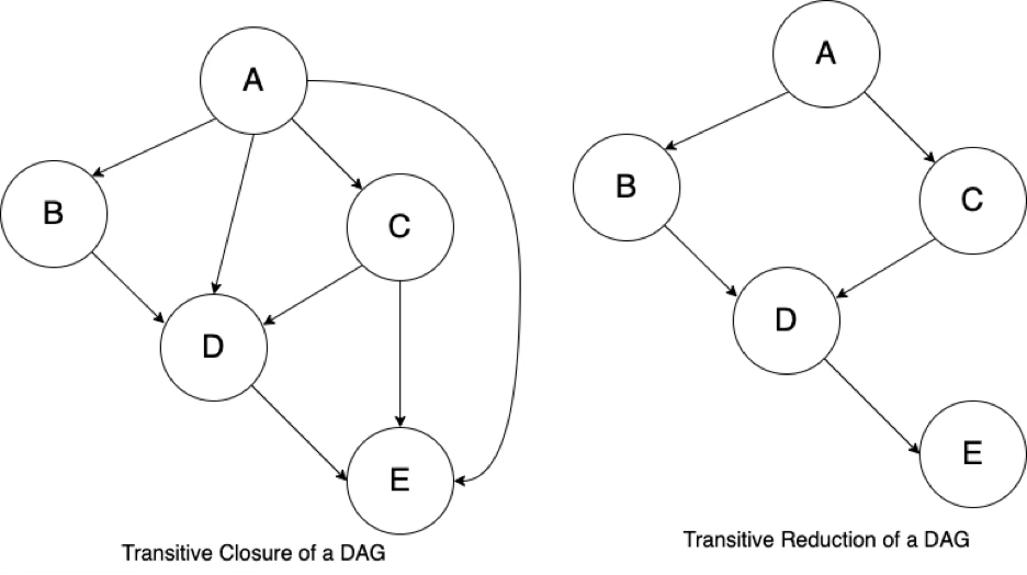
Reachability refers to the ability to navigate from one node to another. The reachability relation of a DAG is an ordering of the nodes in the DAG. The transitive closure of a DAG is the graph with the most edges that has the same reachability relation as the DAG - so the transitive closure can be thought of as a data structure that makes it possible to answer reachability questions. The transitive reduction of a DAG is the graph with the fewest edges that has the same reachability relation as the DAG.
The following diagrams are simple examples of reachability, a reachability relation, transitive closure, and transitive reduction.
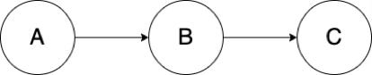
Node B is reachable from A; Node C is reachable from B.
The reachability relation is A -> B -> C.
The transitive closure is A -> C
The diagram below on the left shows the transitive closure of a DAG, showing all of the paths in the graph. The diagram below on the right shows the transitive reduction of the DAG. An orchestration tool like Airflow or Dagster will reduce the transitive closure of the DAG to its transitive reduction.
Summary
DAGs are one of the fundamental concepts in Data Engineering. They essential for designing and visualizing the flow and transformation of data in pipelines. We’ve barely touched on the deep mathematical and theoretical roots DAGs have in graph theory, but they provide a solid foundation for computational processes using DAGs. DAGs represent order of execution and dependencies in a data pipeline and can be used to enable parallel execution of independent processes. Some of the most common and popular tools in data engineering support the definition and execution of data pipelines as DAGs. Understanding DAGs and their properties is essential for data engineering and every data engineer needs to be knowledgeable about them.